Creating a URDF of a Robot in Autodesk Fusion

Step 1: Get a Robot Design
In all seriousness, not everyone is a great designer, and sometimes we'd love to use an existing robot designed by someone else (the Anki Vector for example), you can always find it Design Repositories like GrabCAD
or
Reverse Engineer a 3D Printing Model (Tutorial Coming Soon)
or
Follow the Mechanical Drawings (Good luck finding em), Hope that the text-books are relevant (Yup, that thing in your bag, made of paper) and make your own directly in Autodesk Fusion
Step 2: Create a Project in Fusion
This is just to keep things organized , so its completely optional
Step 3: Upload the Design Files
You dont have to follow this bit tooth n nail
I personally go for a file structure as follows:
.
└── Fusion Project/
    ├── bin/
    │   ├── part1
    │   ├── part2
    │   ├── .
    │   ├── .
    │   ├── .
    │   └── partX
    └── Assembly/
        └── Assembly_Full
Step 4: Make the Full Assembly
This is my favorite part, still feels like Tony Stark
After Creating a new file called Assembly_Full in your Assembly Folder, lets start importing parts from the ground up.
This is a Future-Proofing method that has worked well for me even in clutch situations, where I can iterate quickly by opening the old versions if needed, updating the individual parts in their files, automatically updates the respective component in the assembly, etc.
Assembly_Full is what I call a master design. In this workflow, I copy the master and rename it to a _URDF at the end, as there are a few extra changes to be done to make the URDF. In case, My URDF changes went horrible wrong, somewhere, I can simply delete the _URDF file and create a new copy from the master
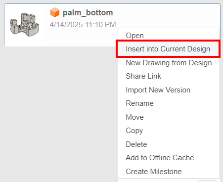
Step 4.1: Importing a Referenced Part into the current Design
- On the Left Pane, navigate to your part of choice
- Right Click on the part
- Import into Current Design
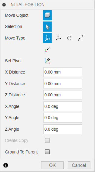
As For the Initial Positions, I leave them in Default in most cases, unless the parts overlap and make life not that easier.
Make Sure that the First Link being added needs the Ground to Parent option disabled, as it will be moving to the World Origin anyway
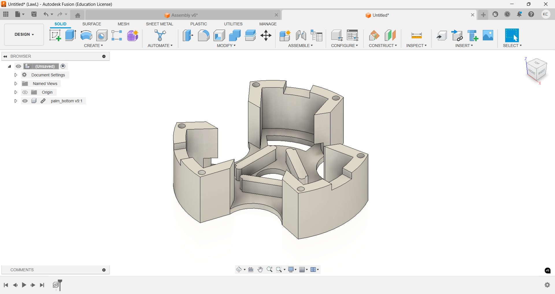
And your Assembly Should Look Something like this:
Step 4.2: Set Part to Origin
By Default the parts you import may not be in World Origin, so lets start by unhiding the Origin.
- Close the Left Pane if you haven't already (Make use of the whole screen, genius)
- In the Browser, Check for a folder called
Origin - Click on the
Eyenext toOriginto Show the Origin in the Assembly - Triple Click anywhere else in the Design to show both the part and the World Origin. It Should Look like something like this:

- Select the part in the
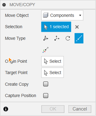
File Browser(Left Pane in the Assembly File) and move the part using theMove Option(Shortcut M) and select thePoint-to-Point Modeusing theMove Option(Shortcut M) and select thePoint-to-Point Mode
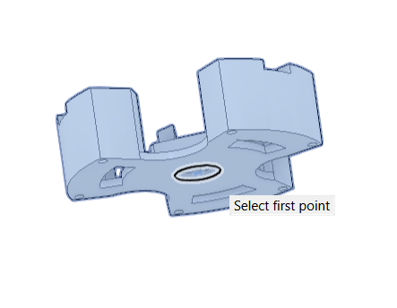
- For the First Point I Chose The Following:
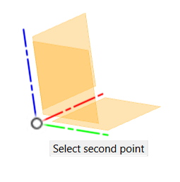
And the Second Point as:
And After the Operation, Ends up looking like the following:

Confirm the Operation by Clicking OK and Hide the World Origin by Clicking on the Eye beside the Folder Origin.
Step 4.3 : Capture Position
In Case you are able to see a timeline at the bottom of the window, then you have Design History Enabled. ( Oh which Timeline you say ?...check with the image below:

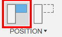
If So, then On the Top-Right of the Window, Click on the Capture Position to not conflict with any future joints that will be created. The Icon looks something like the following (red highlight)
Step 4.4: Ground the Part
In the Browser, Right Click on the Part, and Click on Ground to Parent
This should pop-up a warning message:
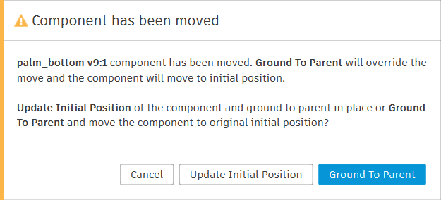
Click on Update Initial Position
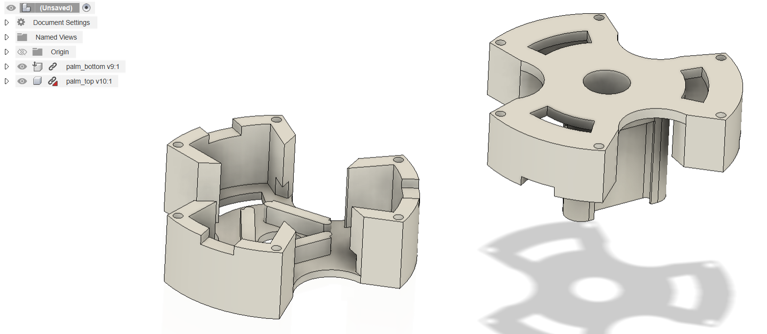
Step 4.5: Add More Parts and Create Joints
For the sake of this tutorial, I'll add one more part into the design, so together, thery look like this:
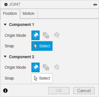
I need a fixed joint, where the top meets the bottom. So Click on Joint (Under Assemble in the Top Panel) or just use the Keyboard Shortcut J
This should open a little widget as follows:
Now here's the tricky part, It needs to follow the logic:
Component-1is the new object that has been added. So in this case ,itspalm_topand my snapping location is like:
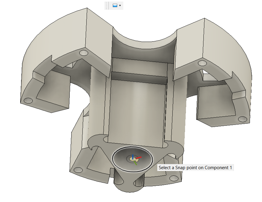
Component-2is the old object that is already in the file. In this case, itspalm_bottomand the snapping position is like:

🪄 The parts join like magic (I find it magical...deal with it) , but its not over yet.
Although in this case, I'm showing a Rigid Joint , You can head to the Motion tab in the Joint widget and change the type to Revolute, Slider , etc. You can also Preview Motion, although not that important for a Rigid Joint, its instrumental with Revolute and Slider Joints especially to identify the Axis of Rotation and the Axis of Slide respectively. The Motion Tab looks like:
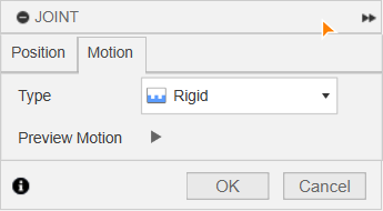
Click OK to confirm the changes.
Step 4.6: Rinse and Repeat
Now Import, the rest of the parts, and join them up like adult lego, or get creative and design your next component around the existing components to the point the assembly looks like a usable robot.
⚠️ Make Sure to Save the file and you can close it
Step 5: Get the fusion2urdf script:
The Repository hosting the URDF Conversion script is here
Open The Zip File, The Contents should look like:
├── URDF_Exporter/
│   ├── utils/
│   │   ├── __init__.py
│   │   └── utils.py
│   ├── package/
│   │   ├── launch/
│   │   │   └── urdf.rviz
│   │   ├── package.xml
│   │   ├── LICENSE
│   │   └── CMakeLists.txt
│   ├── core/
│   │   ├── __init__.py
│   │   ├── Write.py
│   │   ├── Link.py
│   │   └── Joint.py
│   ├── URDF_Exporter.py
│   └── URDF_Exporter.manifest
├── Example
├── README.md
├── LICENSE
└── .gitignore
Copy JUST the URDF_Exporter folder to %APPDATA%\Autodesk\Autodesk Fusion 360\API\Scripts\
The Default Windows Explorer is capable of opening un-encrypted Zip files, but in case you need an archive manager, try WinRAR , 7Zip or Peazip
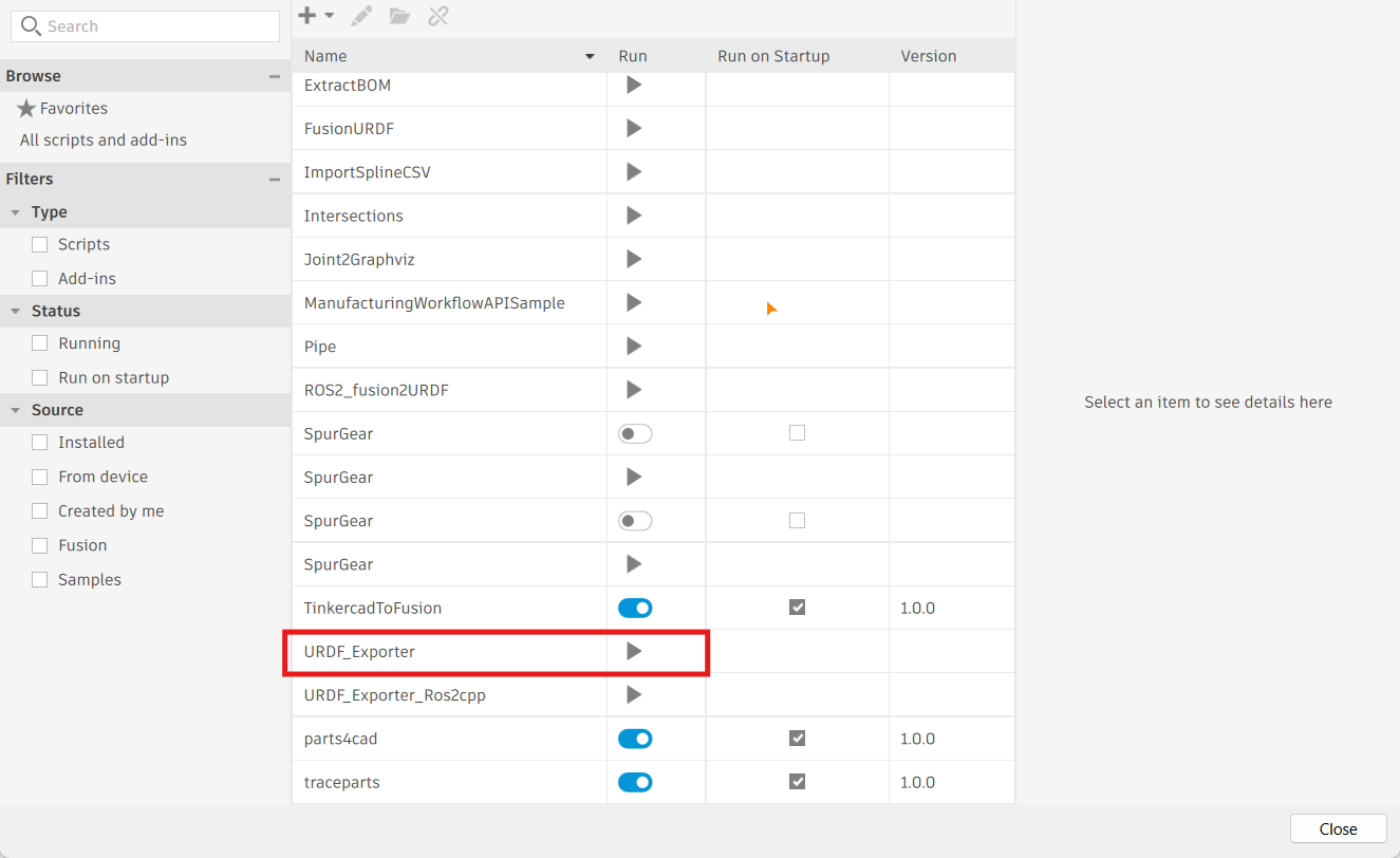
Verify the Install By Opening Utilities --> Add-Ins –> Scripts and Add-Ins and Check for something Called URDF_Exporter. It should look like something like this:
Step 6: Preparing Model for URDF
Step 6.1: Copy Assembly_Full and Rename Copy to something like Assembly_Full_URDF
- Click on the
9 dot menu(Top Left Corner) - Navigate to
Assembly_Full - Right-Click
CopyPaste- Navigate to
Assembly_Full copy - Right-Click
RenameAssembly_Full_URDF
Step 6.2: The Dont's
Step6.2.1 Sub-Assemblies
The repository, doesn't support Sub-Assemblies, Refer to the example below:

Step 6.2.2 Joint Types
The repository on Supports Rigid, Revolute and Slider Joints ONLY, so avoid other joints like Cylinderical, Pin-Slot, Cylinderical, and Ball Joints
Step 6.3: The Do's
Step 6.3.1: File Heirarchy
The Final Assembly (multi-cube icon) should have only Components(cube icon), as seen below:

And Each Component (cube icon) should have only Bodies (silver cylinder icon) and not Meshes (Orange Cloth like icon) as seen below:

Step 6.3.2: Break-Links
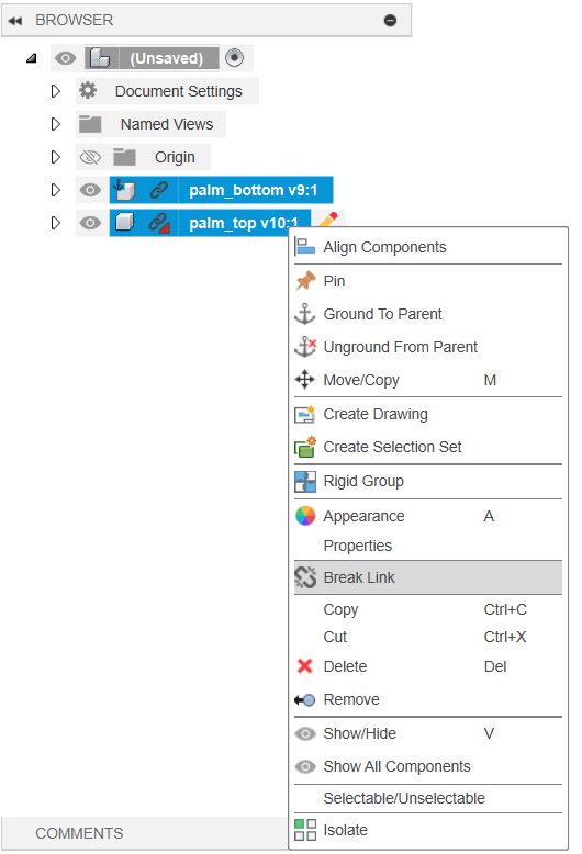
If you see a Chain Icon against your Components, that means they are referenced, The script has a few issues while running while linked, to mitigate the issue:
- Select ALL Components with the
ChainIcon in the File Browser - Right Click
Break-Link
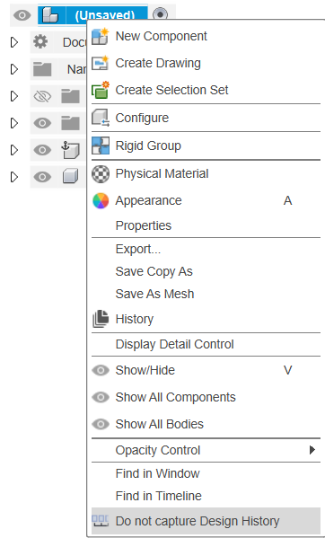
Step 6.3.3: Do Not Capture Design History
Its a Suggestion from the author of the script
- Select the Top Assembly in the File Browser
- Right Click
Do not Capture Design History
Step 6.3.4: Reduce the number of Joints (Rigid)
As 2 Components that are bonded by a Rigid Body, can be treated as a single body, it makes more sense in the resultant URDF as it becomes easy to control, with only the driving joints in the URDF.
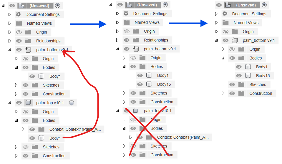
In Step 4.5, I've joined palm_bottom and palm_top using a Rigid Joint, but after the link is broken, You can drag the Body from palm_top to palm_bottom and then delete / remove the Component palm_top, Refer to the flow below (Blue Arrows):
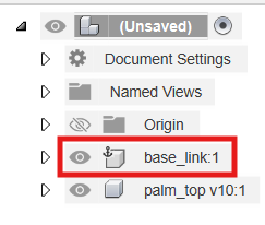
Step 6.3.5: Rename the Grounded Component to base_link
As per the instructions, the component that has been grounded is to be renamed to base_link (Make sure that the Links are Broken)
Step 7: Run Script and Create URDF
Refer to the end of Step 5, but this time run the script by clicking on the Play button.
This will prompt a File Explorer , this the Destination of where you want to export your URDF files
It will take a few seconds, depending on the complexity of the Robot and finally Display a Message Called URDF Exported Successfully
Step 8: Edit the URDF
The Generated URDF has issues with not being compliant for ROS1/ ROS2 Work, primarily due to inconsistencies in the materials. So you need to either comment (Recommended) or remove the parts which mention the material in the URDF.
Open the Folderwhere the URDF was Generated in VS Code or any Other editor of Choice- Open the URDF File
- Search for the following lines:
<material name="silver">
  <color rgba="0.700 0.700 0.700 1.000"/>
</material>
and Replace them lines with:
<!-- <material name="silver">
  <color rgba="0.700 0.700 0.700 1.000"/>
</material> -->- Search for the following lines:
<material name="silver"/>
    <material/>
and Replace them with:
<!-- <material name="silver"/>
    <material/> -->
Step 9: Add Custom Visuals
The current Repository exports the meshes in the .stl files which do not have the capability of holding data on materials, shaders and textures. But the URDF file format supports other mesh files like .dae (Collada), .wav (Wavefront) and .ply (Stanford) , which all support the above mentioned
⚠️Support for Collada is currently being deprecated from accessible Softwares like Blender since version 4.5 and above
- Download and Install Blender ( Any Version Works) and Open It
Assuming that the Default Settings are being UsedStep 9.1 Texture Painting
- Clear the Current Stage by selecting all the
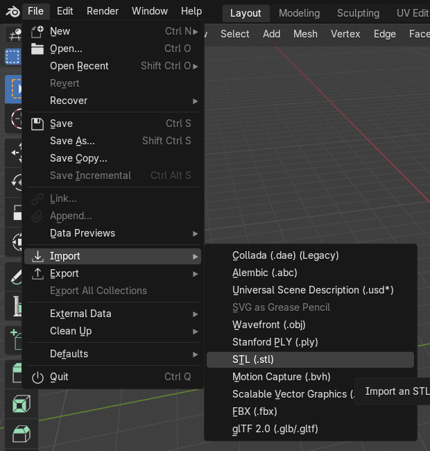
Primativesin the right browser andDelete(Keyboard Shortcut X) - Import an
stlfrom the/meshesfolder in thegenerated URDF folderby
File --> Import --> STL(.stl) --> Navigate to .stl
By Default, The STL file is imported with theYbeing theForward AxisandZbeing theUp Axis
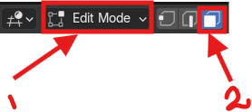
- Switch from
Object ModetoEdit Mode( keyboard ShortcutTab) andFace SelectMode
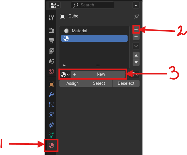
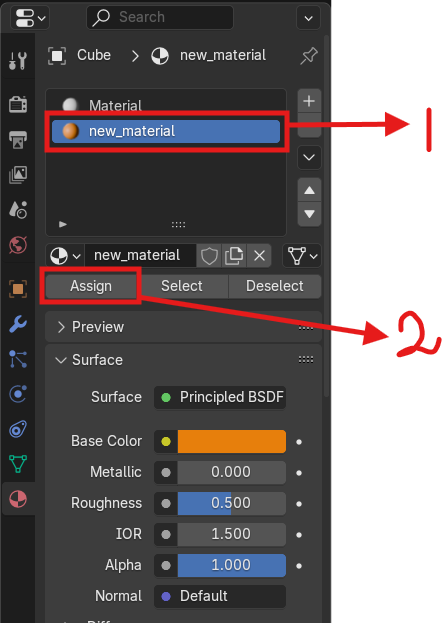
- In the
PropertiesMenu , Click onMaterialsOptions, Click+to add a newMaterial Slotand then onNewto create aNew Material, Refer to the image below.
Renamethe Newly Created Material (Recommended), Change theBase Colorto anyHSVvalue, other properties likeMettalic,Roughness,Sheen, etc. can also be edited. Refer to the Image Below:
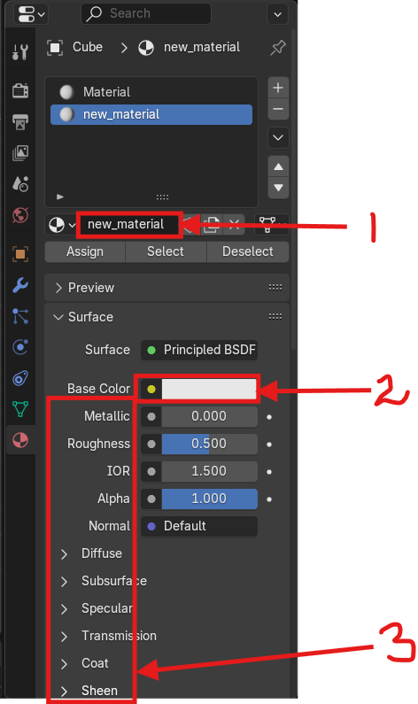
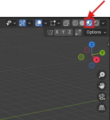
- Change the
ViewporttoShading Mode, Refer to the Image Below
- While You are in
Edit Mode, useCircle Select(Select-->Circle SelectorKeyboard Shortcut C) to select the faces that you want to change appearance of.
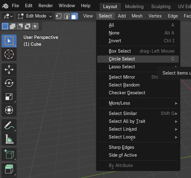
TheRadiusof theCircle Select cursorcan be varied using theScroll Wheelon theMouse
- Then in the
PropertiesMenu, select theNewly Created Materialand click onAssign., Refer to the Image Below:
- Create new Material Slots and Materials as per requirement to Change the appearance of the Mesh
Step 9.2: Export Textured Mesh
- Make Sure that there is only
one meshbeing Textured at a time - Switch back from
Edit ModetoObject Mode - Select the Mesh
- In the Top Taskbar.
File-->Export-->Standord PLY (.ply) - In the right Taskbar (
Operator Presets)....InGeneralmake sure that theForward Axisis atYandUp Axisis atZ. - In
Geometry, I have enabledUV Coordinates,Vertex Attributes,Apply Modifiers.
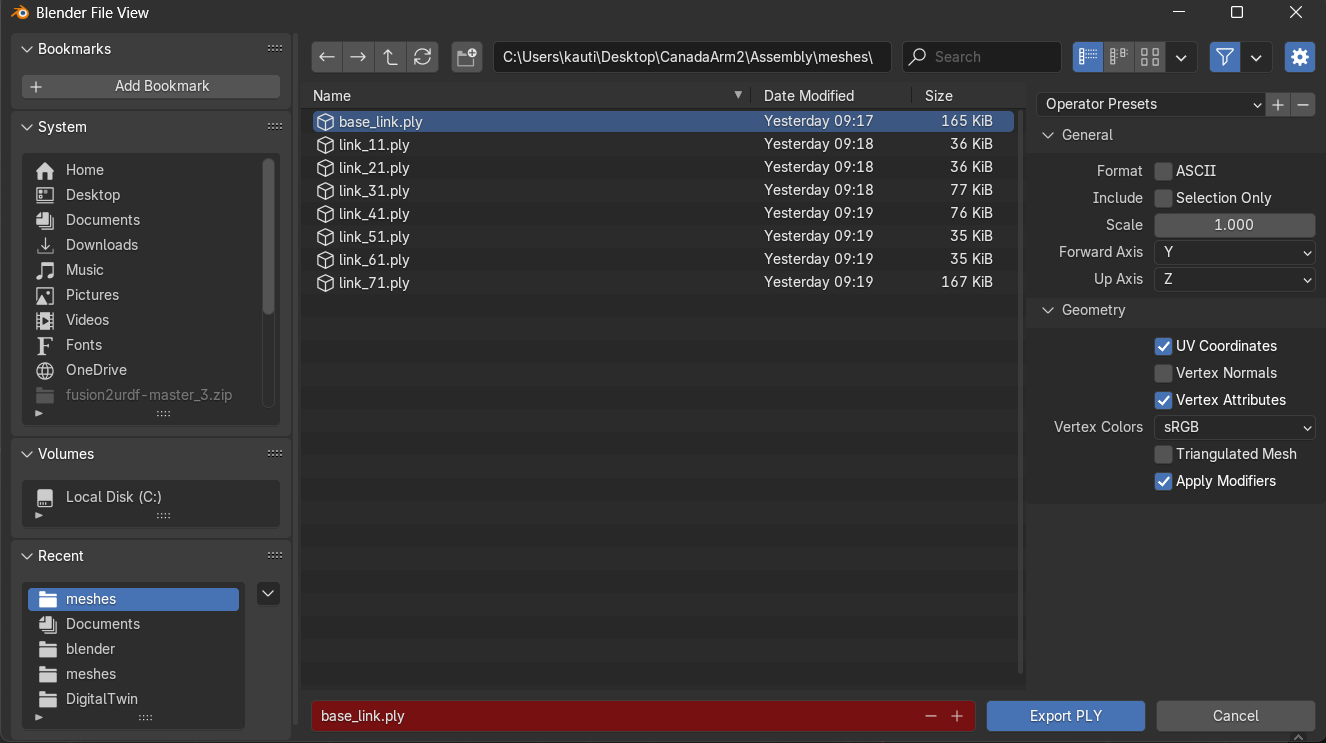
- If the
base_link.stlwas imported then make sure that it is exported asbase_link.plyin the same location(/meshes).
Step 9.3: Repeat 9.1 and 9.2 for all other meshes of the Robot
Dont Worry! The process takes even lesser time with practice... keep at it (Or help me make a new tool...Thanx in Advance)
Step 10: Modify the URDF to use .ply instead .stl
Since the .ply files are saved in the same location as the .stl files, this final modification is pretty straightforward and simple.
- Open the URDF file in VS Code.
- Search (Ctrl + F) for
.stl - Replace (Ctrl + H) with
.ply - Save (Ctrl + S)
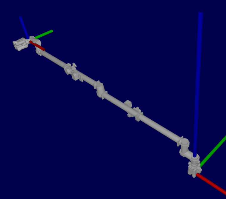
Validation
Now to Visualize the URDF, we use the urdf-viz project.
Installation
Linux:
sudo apt-get install cargo cmake xorg-dev libglu1-mesa-dev -y
cargo install urdf-viz --features assimp
Windows:
Download the windows the Binary from the Releases page of the urdf-viz Project and extract .exe file in the same location as the .urdf file.
Usage:
Linux:
- Open the Terminal
cd path/to/urdf/folder
urdf-viz robot.urdf
Windows:
- Open Terminal (CMD)
cd path/to/urdf/folder
urdf-viz.exe robot.urdf
OR
- Open Terminal (Powershell)
cd path/to/urdf/folder
.\urdf-viz.exe robot.urdf
Output: